V12 Inlet Manifolds
The basic V12 EFI inlet manifold dates back to about 1969, when it was originally designed for use with the AE Brico electronic fuel injection system. It represented the state of the art of that time. With current thinking the manifolds would be designed with longer tracts and larger plenum chambers but by happy chance the air filter boxes become coupled as part of the total plenum volume when the throttles are wide open, which can benefit resonant actions within the system.
The ribbed top of the plenum was originally slightly curved and I remember such manifolds still being used on prototypes with D Jetronic injection in about 1974. The manifold top was levelled off around that time before entering full production.
I have a drawing dated 1977 which defines the size of the tracts at the manifold/head face as being machined to 1.35” (34.3 mm) diameter or 1.43 sq. in. Internally the tracts were as-cast and slightly smaller at around 1.3” (33 mm) diameter.
The internal geometry remained the same for all manifolds until the badged top type were introduced for 92 MY. From then onwards the as-cast sections of the tracts were increased slightly to approximately 35 mm internal diameter. This is why these manifolds are lighter than the previous ones. The material also changed and these later manifolds do not machine or weld as easily as the earlier ribbed top types. They also have a better method of locating the injectors, clamped with O rings by the fuel rail, instead of being fed through hoses as before. The tracts of earlier manifolds had been surprisingly easy to deflect out of alignment so the badged type were joined at the port face to provide much improved rigidity.
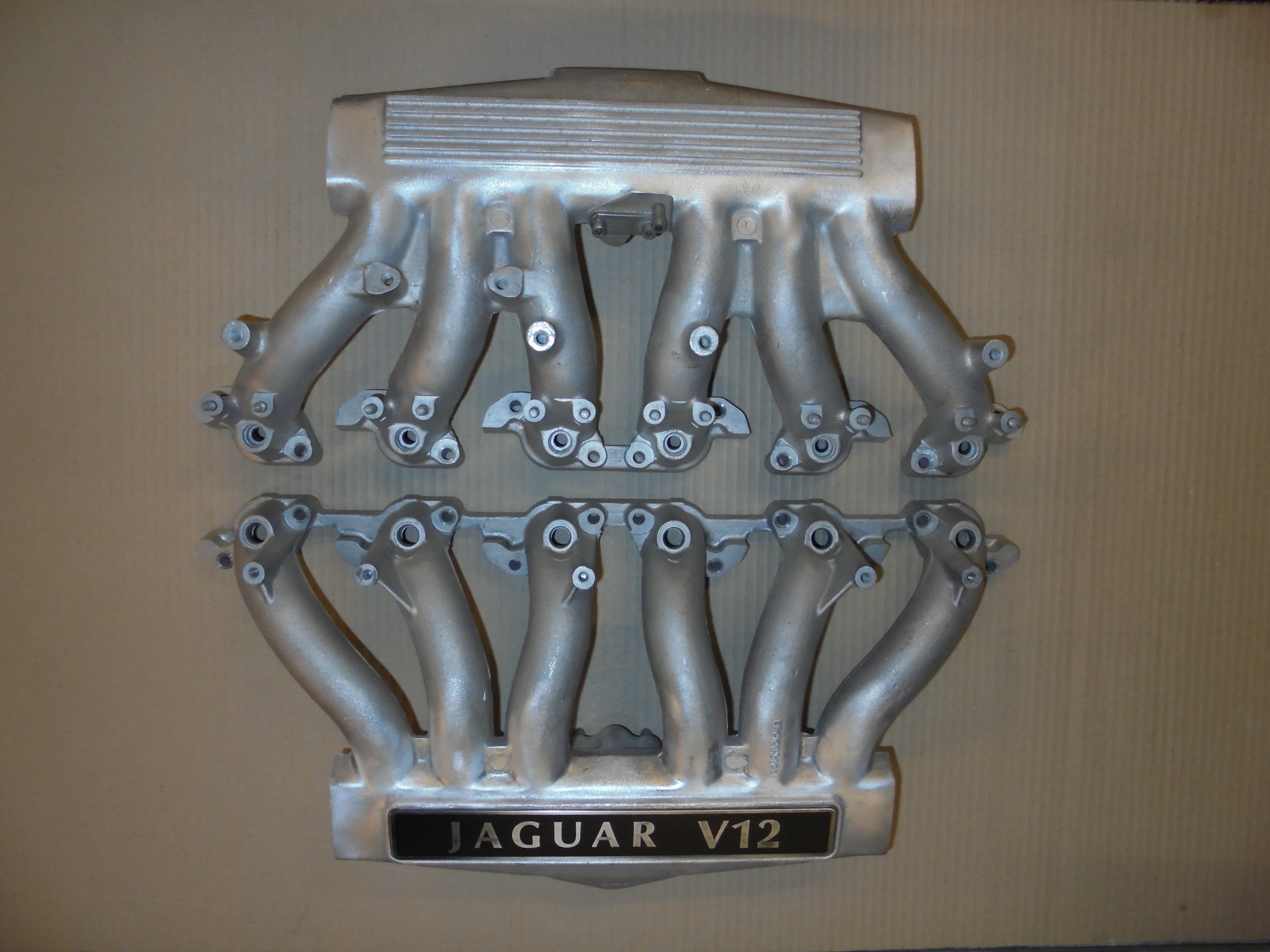
Badged and previous ribbed manifold types.
The TWR Group A inlet manifolds had slightly expanded tracts with an internal diameter of 36 mm. We found long ago that it is possible to safely open out even the standard manifolds to about 37 mm i.d. but this does necessitate cutting the manifolds open and reassembling them afterwards. This tract size would only be of use for a highly developed engine and would be far too big for most normal applications.
Core shift is very common and we have found that the boring operations for inserting the bellmouth extensions for our high torque versions have to be centred individually for each tract and manifold. Even so we still sometimes get breakthroughs which have to be welded and re-machined. These bellmouth inserts have an internal diameter of just over 35 mm and the tracts are fettled to blend smoothly with this size.

Cut-open V12 inlet manifold bored to accept bellmouth extensions to boost torque.
Not only is core shift common, the exact shape and size of the tracts can vary according to the quality of the cores and we have occasionally seen manifolds with significant flash or casting lumps obstructing the inside of the tracts in places where it would never normally be seen or be accessible.
Externally the injector mounting method changed when the badged tops were introduced and the pipe tappings underneath have changed numerous times over the years whilst other details like the HE Lucas ignition amplifier mounts and cold start injector points have come and gone.
Essentially the design is still recognisably much the same as those early Brico prototypes.