A Note about Idle Trim Adjustment
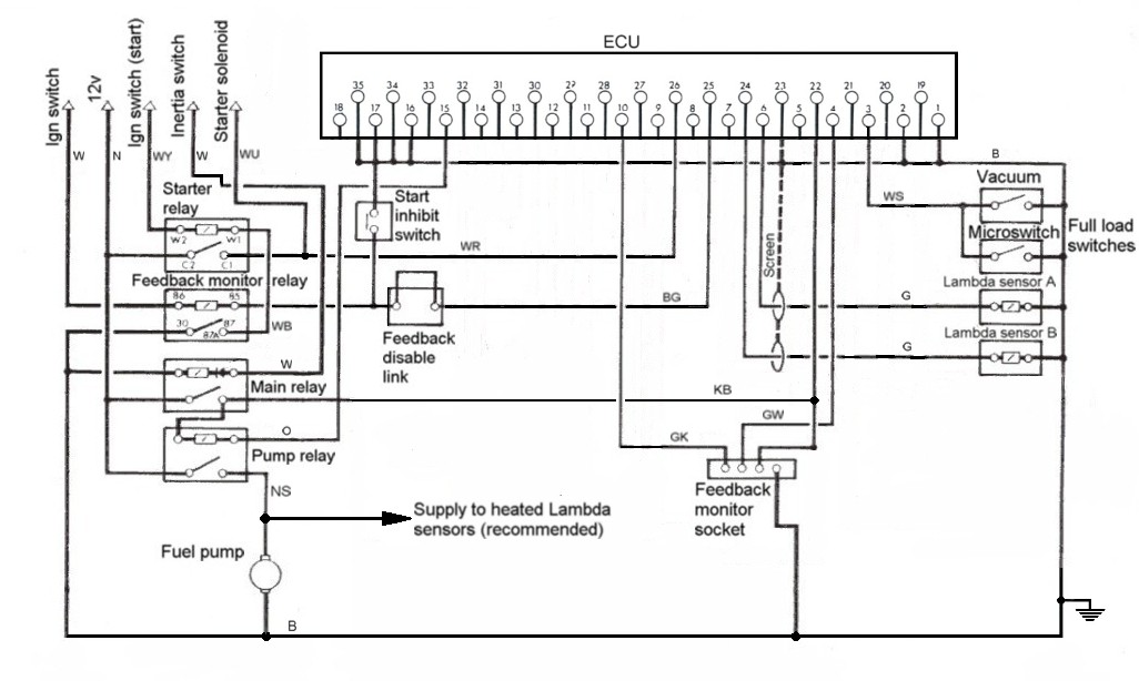
6CU, 8CU and 16CU with Lambda FeedbackTo avoid an unstable idling condition the original system used the transmission inhibit switch to disable feedback when idling in N or P. The instability is aggravated by the low exhaust temperature at idle allowing the Lambda sensors to fall too close to, or even below, their minimum operating temperature.
The disable function could itself be disabled by removal of a link so that idle adjustment could be safely made in N or P guided by the outputs from the Lambda Feedback Monitor Socket. Some people claim that the disable link should be removed when the car is “smog tested” but that is not what it is there for at all and a knowledgeable tester might be inclined to fail the car for having illegal tampering with its emission system. In practice that isn’t likely and removing the link will probably help a marginal car to pass but it is still a bodge that shouldn’t be necessary for a healthy, properly adjusted car. Of course if heated Lambda sensors are fitted then they will function correctly whilst idling so the Lambda disable link is no longer necessary.
6CU.
Obviously the two cylinder banks are corrected independently by the Lambda sensor signals and the monitor circuit provides access to check the state of feedback on each bank seen as voltage outputs which rise and fall slightly according to the direction of feedback correction. The signals relate to the feedback state in the following way:-
High monitor V = Low Lambda signal = ECU corrects in rich direction.
Low monitor V = High Lambda signal = ECU corrects in weak direction.
An LED setting tool with pass/fail lights was available but the aim was simply to get both monitor outputs reading as near to 2.5 volts as possible, which can easily be measured with a voltmeter. The monitor outputs are via a four way plug near to the ECU. The green/white wire reads A bank, the green/pink wire for B bank. The disable link must be removed first.
Lambda feedback additional wiring – click on to expand.
8CU.
This variant is quite rare and was only used on a small number of XJS 3.6 cars for the US market.
This can be considered to be a single bank version of the 6CU with the single Lambda sensor connected to the ECU via pin 6 and the monitor signal available on the green/red wire from pin 4. In other respects the comments for 6CU apply.
Note: There were also some grey import 3.6 cars that were equipped with an aftermarket emission system to which these notes do not apply.
16CU.
Unlike the 6CU the monitor outputs from a 16CU take the form of a square wave with high to low duty cycles representing the amount of correction applied. The waveform can be observed with an oscilloscope but fortunately a 47 uF capacitor across the leads of a voltmeter will convert the signal to a voltage so a voltmeter can be used in the same way as for the 6CU, except that the maximum voltage can vary slightly depending on the processor source at the time of manufacture. The mid-range point can therefore also vary but can be approximated as 2.25 volts.
Later cars were delivered with heated Lambda sensors and could therefore idle satisfactorily in feedback so have no need for the Lambda disable link.
There is always likely to be a minor difference between the ideal setting for each of the two cylinder banks.

