Jaguar V12 – Radiator And Cooling Issues
The Cooling System.
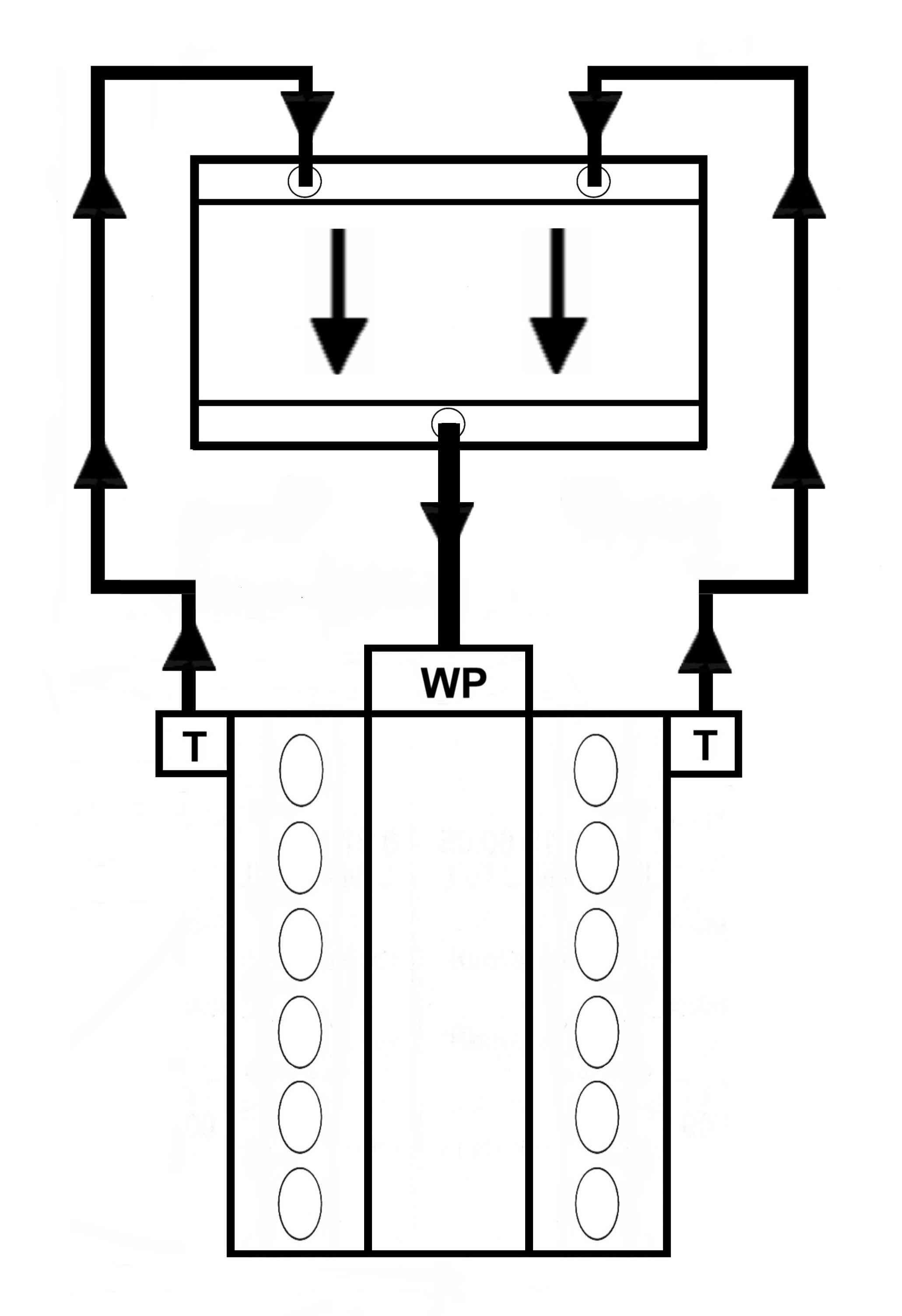
The first car to be powered by the Jaguar V12 engine was the Series Three E Type introduced in 1971. Whilst earlier 6 cylinder E Types had employed a cross-flow radiator the V12 reverted to a downward flow, single pass, radiator (Fig. 1). The two cylinder banks flowed into opposite ends of the radiator top tank from where coolant flowed downwards through the matrix core to emerge into the lower tank, exiting from the centre then back to the water pump (WP) on the front of the engine. The flow quantity from each bank was determined by the two thermostats (T) which also deflected flow to a bypass system direct to the pump when closed.
This arrangement was not ideal because it was known to produce significant pressure drop, did not really have adequate spare capacity for high demand conditions and because the engine was composed of corrosion prone aluminium castings, was intolerant of neglect.
It probably only avoided serious criticism because of the open nature of the E type engine bay and the air venting upwards through the bonnet.
Fig. 1. Essentials of the V12 E Type cooling system.
A much more efficient cooling system was necessary for when the V12 found its way into the XJ12 saloon and the forthcoming XJS. The insistence for styling reasons that no upward or sideways venting would be permissible was not helpful but wasn’t really significant because cooling air would always find its way out below the engine.
A prototype XJS was modified to have an upward venting radiator through a large slot at the forward end of the bonnet, similar to many race cars of the period, but it was deemed not to be a practical solution.
Cross-flow radiators were becoming popular for modern cars with a low bonnet line which tended to preclude a vertical flow radiator because of the space required for the top and bottom tanks. It was no surprise then that when the XJ6 saloon was first launched in 1968 a cross-flow arrangement was the obvious choice.
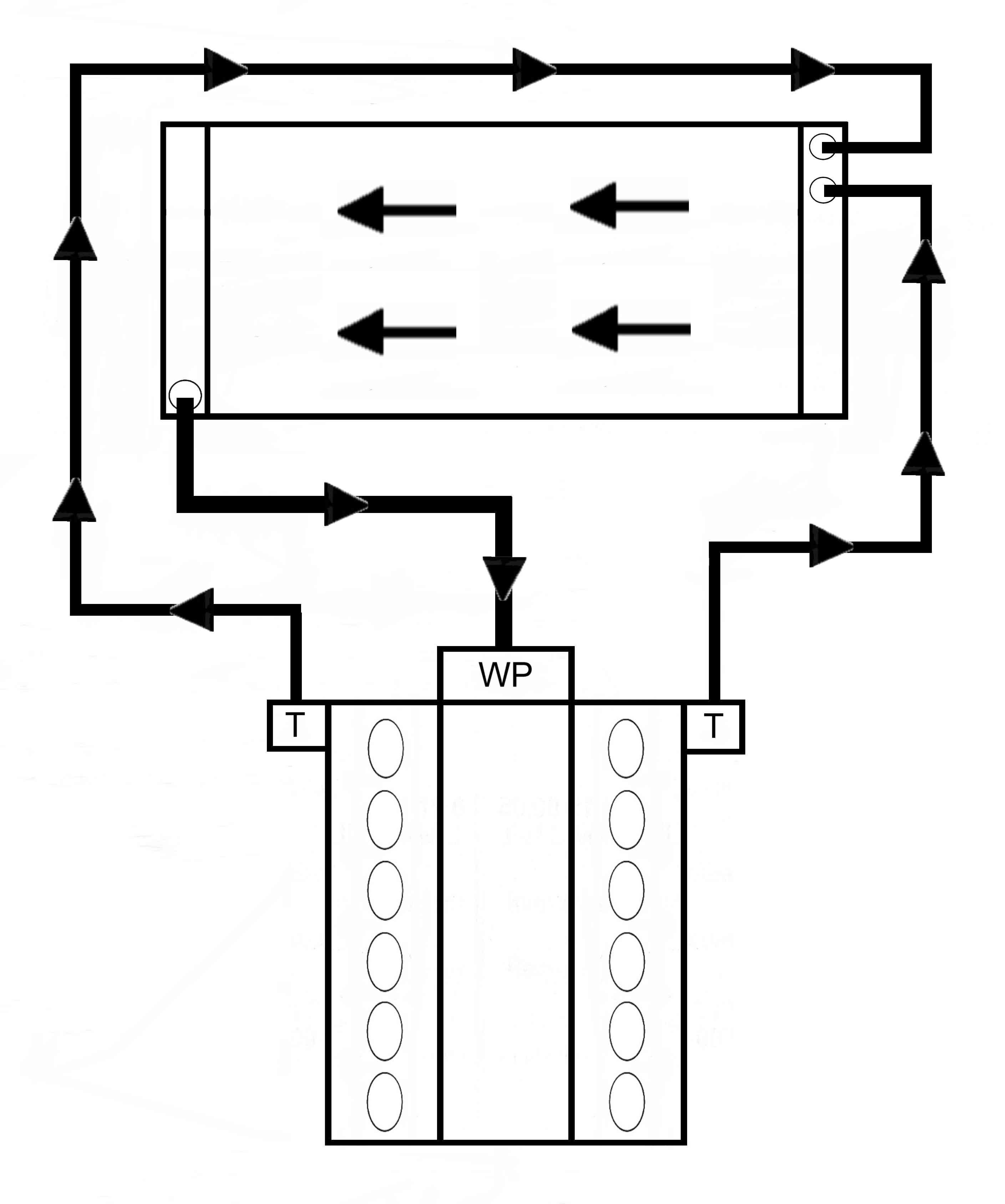
Fig. 2. How a single pass system might be arranged for an XJ12/XJS cooling system.
When the XJ12 arrived in 1972 there was no reason to depart from the cross flow layout despite the inevitable complication of having coolant discharging from both sides of the engine.
Of course, one might suppose that merging the outflow from both banks into a simple cross-flow radiator (Fig. 2) would be a straightforward solution.
There is a problem that coolant from one bank would then have to be piped across the engine bay, which entails some measure of viscous drag that would not apply equally to flow from the other bank. Short pipe runs are preferred whenever possible.
There is also need to ensure that the two streams of coolant can merge without one becoming biased over the other, which is not always as simple as might be supposed.
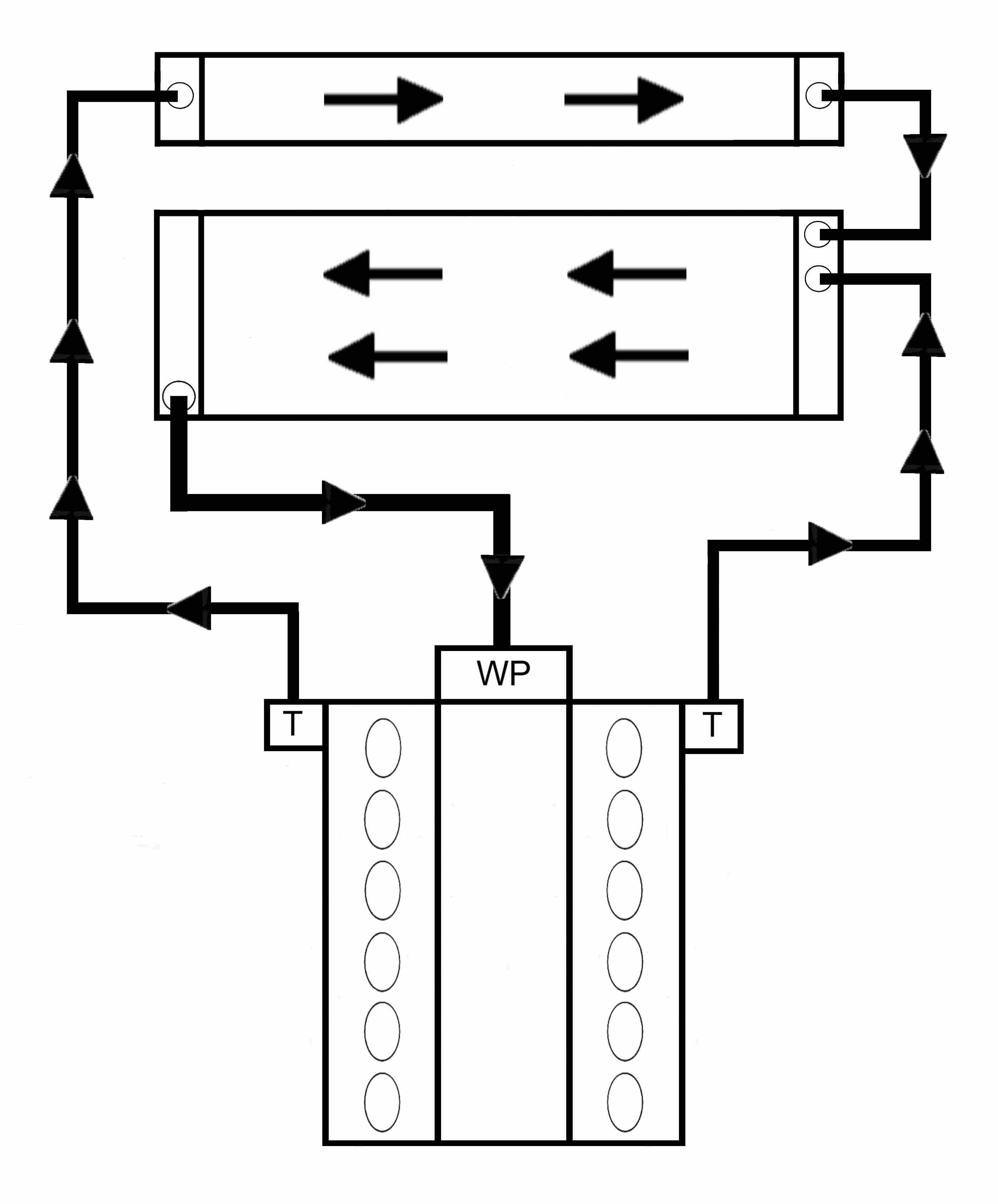
Jaguar’s engineers reasoned logically that if B bank coolant has to cross the engine bay it might as well do so via a radiator rather than a pipe, then it could merge with A bank coolant as it entered the main radiator which could now be reduced in size (Fig. 3).
Fig. 3. An alternative way of looking at the XJ12/XJS cooling system.
This evolved into a single large radiator with a divider inside the LH end tank so that coolant entering on that side would flow across the top 1/3rd of the core before joining the flow entering on the right then passing back through the lower 2/3rds of the core (Fig. 4).
Fig. 4. Essentials of the XJ12/XJS cooling system.
Crossover plumbing was now avoided and B bank flow out of the end of the radiator top section would merge easily into the flow from A bank, passing downwards to the lower section.
As far as B bank is concerned this is a double pass radiator but for A bank it is a single pass system with the return feed from the outlet back to the pump common to both.
Coolant from B bank therefore flows across the radiator twice whilst that from A bank crosses just once. On average then all the coolant flows across the width of the radiator 1.5 times. Now the equivalent single pass radiator would flow all of the coolant across once so the flow velocity would be 2/3 of the arrangement chosen by Jaguar. This can be significant because increased flow velocity produces more disturbance of the boundary layers in the tubes and therefore increases heat transfer out to the passing air.
The cross-over radiator is therefore a more efficient heat exchanger than a simple single pass radiator. This explains why it appealed to the engineers at Jaguar and why it was used on every V12 model except the E type. Early proving testing had included successful trials in extreme environments like Death Valley.
The temperature drop across the radiator is normally in the range of 5 – 10°C and the rise across the engine must be of the same magnitude although the spread may increase at low engines speeds when coolant flow is relatively slow.
The Downside.
Although the cross-over arrangement works well in normal conditions it has an unfortunate tendency to create unbalanced flow if the radiator tubes start to become restricted by build-up of deposits.
Although deposits might equally affect all of the radiator, any restriction to flow from B bank allows more coolant from A bank to pass across the larger lower section of the radiator so A bank is able to increase its cooling capacity at the expense of B bank.
A consequent rise of temperature in B bank will open its thermostat more to compensate but eventually the limit of the thermostat will be reached and B bank will then be in danger of overheating. Meanwhile A bank will be continuing to function at a comparatively normal temperature and as this is the side where the temperature gauge sender is located the gauge will not indicate anything untoward.
The Solution.
Because the problem is unlikely to arise if the radiator is kept free of deposits it is important that the correct proportion of specified corrosion inhibitor/antifreeze is used in the coolant and that it is changed regularly as recommended (XJS Repair Operation Manual page 09-2).
It would also be a good idea to move the temperature gauge sender across to B bank thermostat housing, or have a means of monitoring temperatures on both sides.
It is probable that very few of these cars have the coolant changed annually as recommended but the writer did once encounter a pristine, one-owner, scrupulously maintained XJ12C which had to have the heads removed after 10 years during a performance upgrade. Both heads lifted with ease and the head faces were clean almost like the day when it had been built. Not many V12s are like that.
Modern coolant fluids and additives are probably a lot more effective so changing coolant on recent cars is virtually unknown but the V12 is from a different era when few engines were made from aluminium alloys and it required a more meticulous approach than people were used to at the time.
Increasing the Margins.
Extra electric fans installed ahead of the radiator will increase the cooling efficiency in low speed/high temperature conditions in climates where this might be thought advisable.
The flow rate of the V12 coolant pump was determined by the requirement when idling and in consequence is much too high at maximum engine speed.
To avoid the possibility of cavitation at high speeds, racing V12s using the standard pump should have the pump speed reduced by about 20 – 30% which also reduces the parasitic loss of driving the pump. This would not normally be advisable for a road car but an auxiliary electric pump could be added to improve the flow rate at low engine speeds and can also maintain flow for a set time after the engine is switched off. This can be very important because when a V12 overheats, for whatever reason, it is in the period following switch-off that valve seats can become detached. The combination of an electric fan and electric water pump can preserve an engine that might otherwise suffer badly.
A larger electric pump could be used as the main generator of coolant flow but because the water passages across the timing chest into the cylinder block are designed to accept and direct the flow from a centrifugal impeller it is wise to retain it, but with the blades reduced in area. A pump with a flow rate of about 150 litres/minute should be more than adequate.
There is a school of thought that the coolant passages from the heads into the water rails of the V12 should be fitted with graduated restrictors to promote flow to the back of the cylinder head. Whilst it seems intuitive that this would rectify any inequalities of coolant temperature flowing out of the heads at low flow rates it should be remembered that intuition can be an unreliable guide.
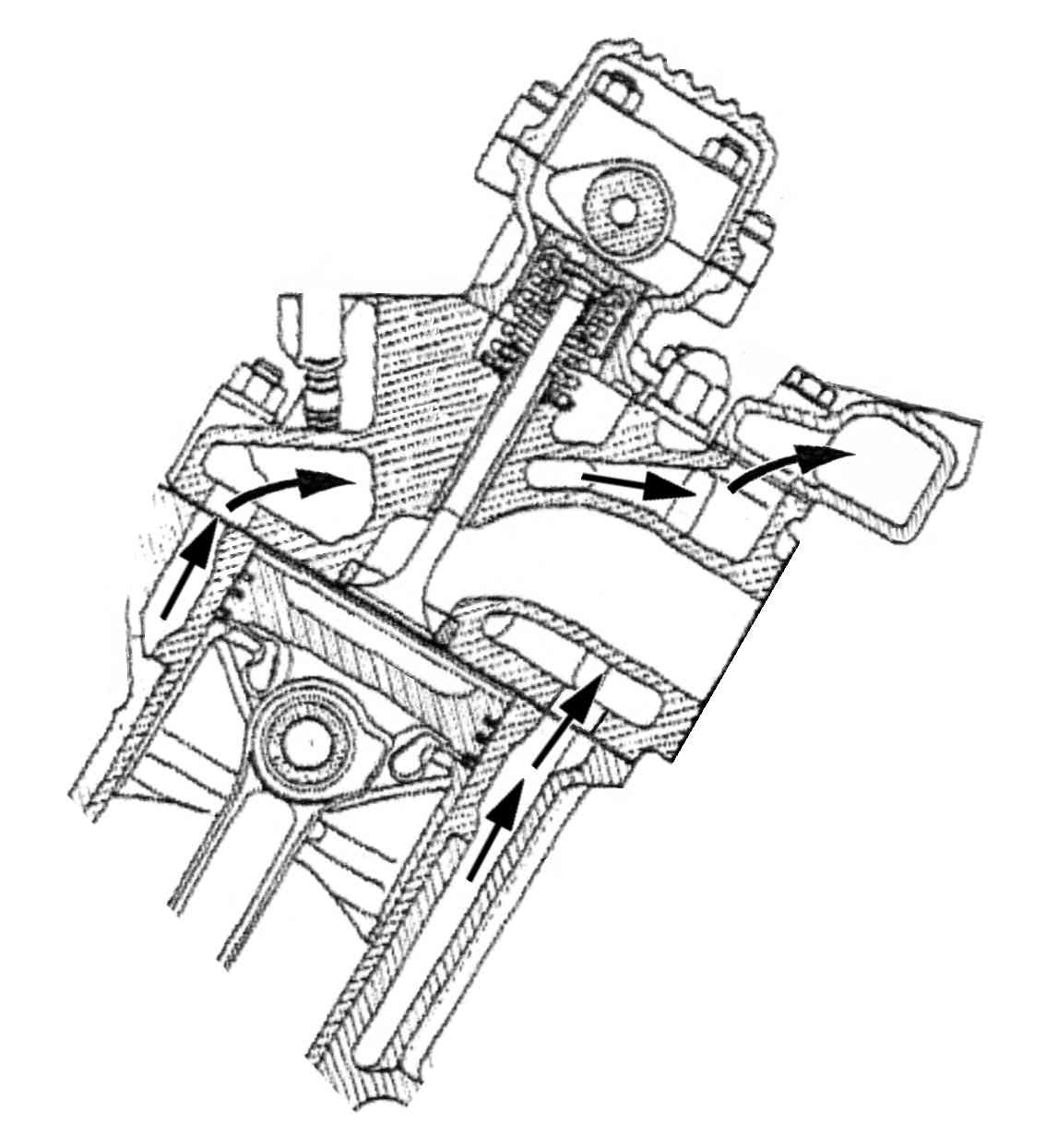
After flowing all around the engine the coolant flow finally passes around the exhaust ports (Fig. 5) which are always a major source of heat loss to coolant. An exhaust port where the flow rate is slower will inevitably increase the coolant temperature locally but this does not mean the temperature further back around that cylinder or combustion chamber is significantly different from any others. Any such temperature rise cannot be very great or steam pockets would be able to form, ejecting coolant from the pressure cap, which will only happen if the engine is already in a serious overheating situation.
Fig. 5. Coolant flow through V12 head.
Engines do not overheat because of differing flow rates along the engine; they overheat because the heat being produced by the engine cannot be dissipated sufficiently from the radiator. When V12s do overheat badly enough to drop valve seats it can happen at any cylinder and is largely determined by whichever valves are open following switch-off. The excessive expansion of overheating exhaust valve seats is likely to make them all less secure anyway.
It is perhaps relevant that when Jaguar introduced the final V12 saloon, the X300, the rear water rail sections were eliminated to make space for electric idle control valves. The cylinder head casting was unchanged so flow from the back of the engine could then only flow forward along the heads to the remaining coolant outlets, apart from a route from the LH head for the heater circuit. It is inconceivable that this was done without being thoroughly tested and there does not seem to be any evidence of these cars suffering any increased tendency to overheat.
Thermostats.
Until about 1977 the Jaguar V12 was fitted as standard with 82°C thermostats which then changed to 88°C. This gave a small improvement in fuel consumption on the CAFE Highway Test but there was no significant effect on emissions which at that time were most critical long before the thermostats start to open.
It is a common fallacy that this made the engine more at risk of overheating because the thermostats merely set the lower limit of the normal operating temperature range and have no control of the maximum temperature. An engine that overheats with 88° thermostats will still overheat if they were changed to 74° items.
Using a lower temperature thermostat does not offer any protection against overheating. If the radiator cannot dissipate enough heat the system will run hotter until it does – until it reaches the maximum pressure limit of the system.
As well as increasing wear, running at too low a temperature can cause drivability issues through richness and excess acceleration fuelling. A higher operating temperature also helps to prevent moisture contamination of sump oil so there can be several benefits to engine life as long as the oil grade is suitable.
Many years ago it was normal to run racing engines at not much more than 70°C but that was mainly because of inadequacies of the lubricants of the time. Most modern racing engines are designed to operate at around 90°C for maximum efficiency with respect to fuel vapourisation and lubricant performance. In order to reduce drag from radiators F1 engines and some others have been operated at temperatures as high as 120°C.
Coolant Flow Considerations.
The coolant temperature gradient through an engine at operating speeds is generally likely to be between 5 to 10 degrees Celsius. Obviously the gradient across the radiator is closely similar, but in the reverse direction.
Coolant flow through engines was traditionally arranged largely for pragmatic reasons and in most instances the flow enters the engine low down and exits at some point near the top, which permitted use of thermo-circulation of coolant without a water pump, a practice that was quite common until the 1950s. Increasing power outputs required more active coolant flow driven by a pump to handle the increased heat rejection.
Upright engines will therefore have coolant flowing into the cylinder block then making its way upwards through to the head with flow biased towards the exhaust valve seats and ports for obvious reasons, before being discharged to the radiator. Inverted engines, not uncommon for aircraft, have coolant entering the head(s) and then working upwards around the cylinders to exit near the crankcase. Horizontally opposed engines have coolant flow entering the block low down and exiting from the upper side of the heads (usually around the inlet valves).
That being said, because the temperature gradient is only a few degrees there is no reason at all why coolant should not be circulated in the reverse direction if that is more convenient.
An interesting example is Toyota’s 2009 F1 engine, a 2.4 litre 735 b.h.p. V8, which had coolant entering through a primary pump, driving it across both above and below the main bearings then upwards through the right hand cylinder bank and passing from that head down into a secondary pump. The coolant then flowed back across the main bearings by a different route and into the left hand cylinders then upwards to exit from the top of the left hand head. The incoming temperature was 122°C and outgoing was 130°C at a flow rate of around 200 – 220 l/min.
The significance of directing coolant flow around the main bearings is that it provides thermal stability and consistent clearances as well as removal of the heat generated by a crankshaft spinning at 18,000 r.p.m in plain (i.e. oil film) bearings. There are advantages in both friction reduction and extended engine life, both of which are important for modern racing engines.
It also resolves heat transfer from throw-off oil gathering in the lower crankcase chambers from the oil jet cooled pistons. This heat would otherwise be conducted via the upper cylinder walls to the coolant which would necessitate thicker, and therefore heavier, piston crowns.


